Standard Construction Process of Light Steel Keel Gypsum Board Ceiling
Installation Process for Clip-in Metal Furring Gypsum Board Ceiling
Layout marking →Fix the clip-in light steel keel framework (spacing ≤ 600 mm), secured with expansion bolts →Install secondary keels at a spacing of 400 mm →Staggered installation of double-layer 9 mm gypsum boards, with full application of white adhesive between the two layers →Fix gypsum boards using self-tapping screws; apply anti-rust paint to screw heads →Apply anti-rust putty →For gypsum board joints (reserve a gap of more than 5 mm), use specialized jointing gypsum to level the surface →Apply high-quality anti-crack paper joint tape.
Detailed Installation Instructions for Standard Light Steel Keel Paper-Faced Gypsum Board
(I) Site Preparation
Gypsum board installation shall only be carried out after the completion of the building’s exterior wall construction. Installation is not recommended before the exterior walls are finished or before windows are fully installed.
All major in-floor and ceiling service lines, including HVAC systems such as air conditioning and fresh air systems, must be completed and approved through inspection before installing the gypsum board ceiling system.
The installation site must be kept dry. Standing water on the floor is not permitted.
Before installation, the site shall be thoroughly cleaned to remove dirt, dust, oil, debris, and other contaminants.
Any residual cement in the installation area must be removed. Uneven ground surfaces shall be properly repaired and leveled.
During joint treatment works, the on-site ambient temperature must be above 5°C and below 35°C. Installation is prohibited outside this temperature range.
(II) Material Inspection
Before installation, verify that all materials are correct in type, specification, and quantity.
Gypsum boards shall be dry, flat, and intact, with undamaged face paper. Boards that are damp, warped, cracked, broken, or have blistered face paper shall not be used.
Light steel keels shall be straight, smooth, free from rust, and free from deformation.
Joint compound shall be dry, free from moisture, and free from hardening or lumping.
(III) Ceiling Layout and Positioning
According to the design drawings, snap layout lines on the surrounding walls to mark the ceiling elevation and position.
Snap layout lines on the ceiling slab to indicate the hanging point positions for suspension rods.
(IV) Installation of Perimeter Keel
Install the perimeter keels along the surrounding walls according to the marked layout lines.
(V) Installation of Load-Bearing Main Keels
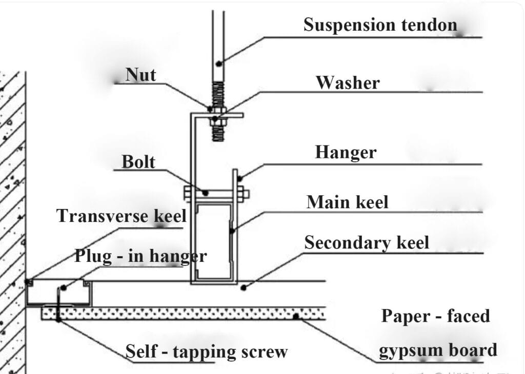
Install suspension rods along the marked layout lines on the ceiling slab. The spacing between suspension rods shall not exceed 1200 mm; a spacing of 900 mm is recommended.
When using angle keels as suspension members, the angle keels may be directly fixed to the load-bearing main keels with screws.
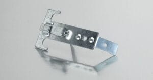
When using threaded suspension rods, connect the suspension rods to the load-bearing main keels using dedicated keel hangers.
The wall-side ends of the load-bearing main keels may be supported on the perimeter keels.
The spacing between load-bearing main keels shall not exceed 1200 mm; a spacing of 900 mm is recommended.
Main keel connectors may be used to extend and connect two load-bearing main keels.
A slight upward camber shall be provided at the mid-span of the load-bearing main keels. The camber height shall be not less than 0.5% of the room’s short-span dimension.
(VI) Installation of Secondary (Cover) Keels
Secondary keels shall be arranged perpendicular to the load-bearing main keels and fixed onto them using clips.
The center-to-center spacing of secondary keels is generally 400 mm; in humid environments, 300 mm spacing is recommended.
The wall-side ends of secondary keels may be clipped into the perimeter keels.
(VII) Installation of Cross-Bracing Keels
According to design requirements, cross-bracing keels shall be installed between the secondary keels.
The spacing between cross-bracing keels is generally 600 mm.
Cross-bracing keels shall be fixed onto the secondary keels using dedicated hangers.
(VIII) Gypsum Board Installation
(Use 12 mm waterproof gypsum boards in bathrooms and kitchens)
Installation of gypsum boards shall start from one end of the wall and proceed sequentially.
Adjacent boards shall be placed closely together, leaving a gap of approximately 5 mm.
Board edges shall be positioned at the center of the keels, with an overlap of no less than 15 mm over the keel.
Side edges of gypsum boards shall be tightly aligned with the wall, leaving no gaps (exceptions apply for soundproof or fire-resistant ceilings).
Apply white adhesive fully between the two layers of gypsum boards.
The second layer of gypsum boards must be installed in a staggered (offset) pattern relative to the first layer.
Self-tapping screws shall be driven in with an electric screwdriver in a single operation.
Screw heads should be recessed 0.5–1 mm below the gypsum board surface; the face paper must not be cut to expose gypsum.
Screws should be positioned 10–15 mm from finished edges and 15–20 mm from cut edges.
Screw spacing along board edges is recommended at 200 mm and 300 mm in the board field (center area).
(IX) Joint Treatment
Prepare the joint compound and let it rest for 15 minutes after mixing.
Fill the gaps between gypsum boards with the joint compound, pressing it firmly. The compound thickness should not exceed the board surface level.
After initial setting, apply joint compound along both sides of the board seams, extending at least 50 mm from the board edge.
Embed the joint tape along the seams and smooth it with a putty knife, ensuring no air bubbles exist between the tape and the joint compound.
Ensure that the centerline of the joint tape aligns with the centerline of the gypsum board joint, and that the tape adheres equally over the two adjacent boards.
Smooth the excess joint compound pushed out from the edges of the tape, embedding the tape fully within the compound.
Allow the compound to set (refer to the manufacturer’s instructions on the joint compound packaging). Apply a first layer of joint compound over the seam, smooth it, extending at least 50 mm beyond the first seam on each side.
Let this layer cure according to the manufacturer’s instructions.
Apply a second layer of joint compound over the seam, smoothing it and extending at least 50 mm beyond the second seam on each side.
Once cured, lightly sand the seam to make it flush and even with the board surface.
For cut-edge joints, increase the coverage width of each joint compound layer by 100 mm.
Related Products
-
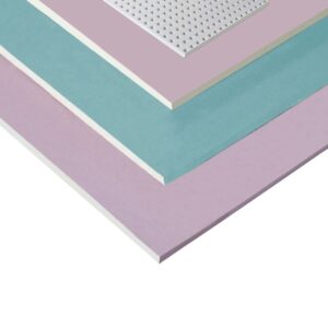
 Formaldehyde-Reducing Gypsum Board Series
Rated 0 out of 5
Formaldehyde-Reducing Gypsum Board Series
Rated 0 out of 5 -
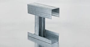
 Shaft Wall Light Gauge Steel Framing System
Rated 0 out of 5
Shaft Wall Light Gauge Steel Framing System
Rated 0 out of 5 -
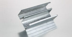
Vibration-Damping Steel Stud System | Acoustic Lightweight Steel Framing for Partition Walls
Rated 0 out of 5
-
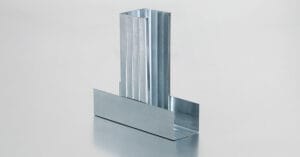
Lightweight Steel Stud System for Partition Walls | Galvanized Metal Framing for Interior Drywall Systems
Rated 0 out of 5
-
Ceiling Framing Accessories Kit
Rated 0 out of 5